aerodynamics · CFD · test
Adaptive camber wing
Simulations & Manufacturing Lead · University of Michigan Aerospace Engineering
Overview
Senior design-build-test project at the University of Michigan developing a wing with continuously variable camber capability. Led CFD simulation and manufacturing efforts. Characterized aerodynamic performance across a structured matrix of camber configurations and angles of attack. The project demonstrated a measurable lift-to-drag improvement over conventional discrete-flap designs, presented to faculty and industry reviewers.
Approach & methodology
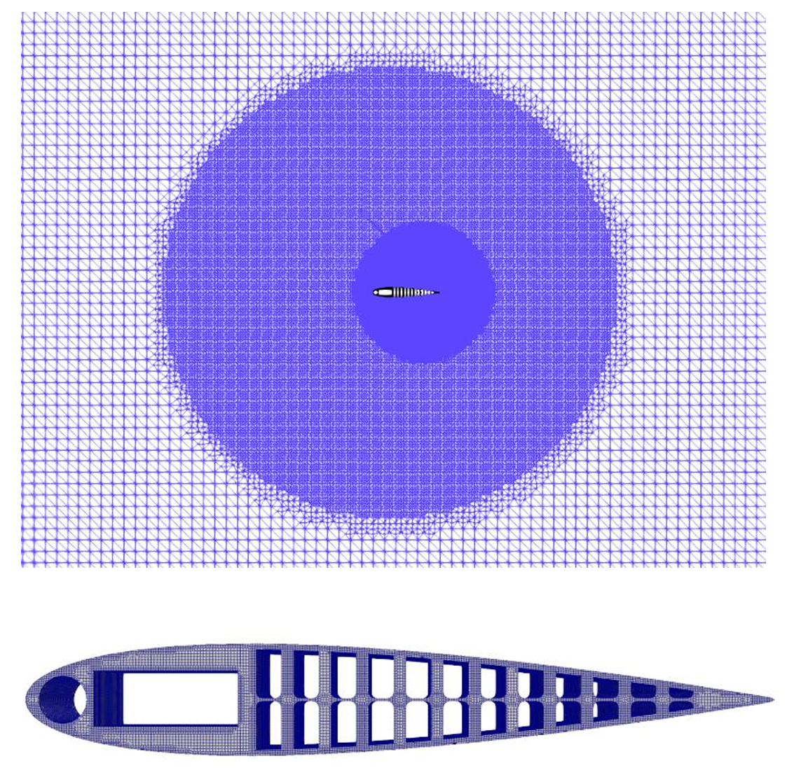
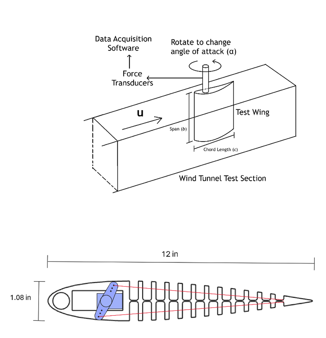
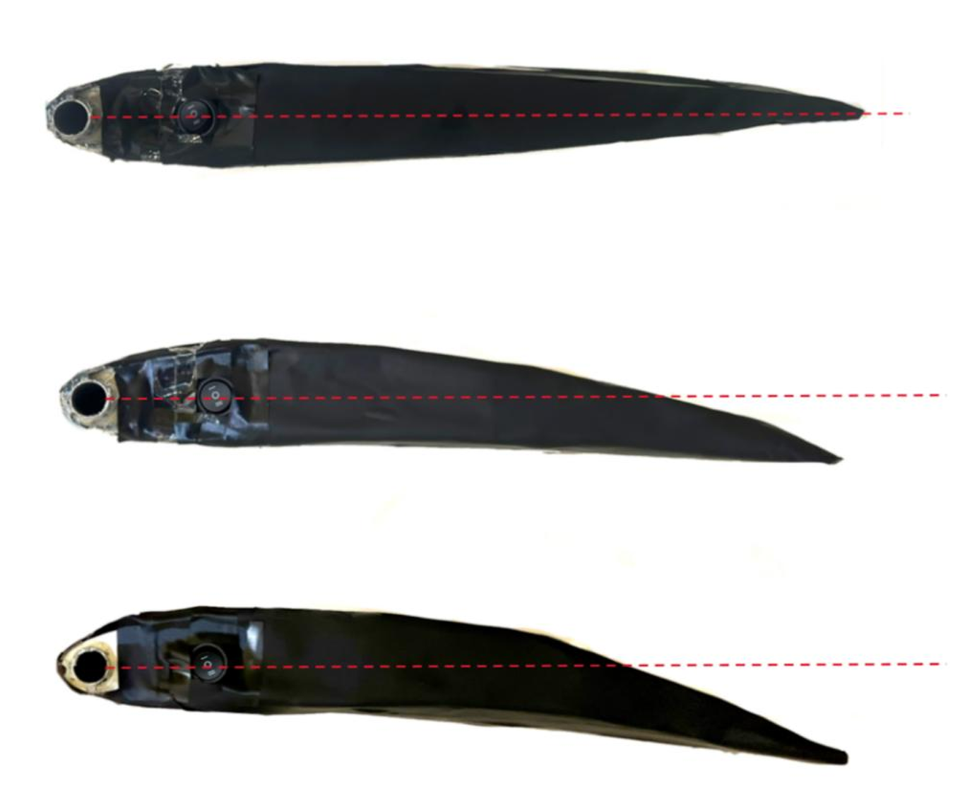
Built a full 3D wing geometry and extracted representative 2D cross-sections for ANSYS Fluent CFD analysis. Mesh refinement was applied as a function of chord length, with additional targeted refinement at the leading and trailing edges to resolve boundary layer behavior and capture flow separation onset accurately. A structured nine-configuration test matrix covered three camber settings (baseline, moderate, and high deflection) at three angles of attack each.
Lift and drag coefficients were extracted from each CFD case, and Cp distributions and flow separation patterns were visualized to understand the aerodynamic mechanisms at each configuration. Teammates led wind tunnel testing used the same configuration matrix for experimental validation, with the physical wing fabricated to match the CFD geometry. Correlation between CFD predictions and tunnel measurements was assessed across the full test matrix.
Tools & techniques
ANSYS Fluent (steady RANS CFD), ANSYS Meshing (chord-length-based structured refinement, LE/TE edge sizing), University of Michigan low-speed wind tunnel, force balance and pressure tap data acquisition, Cp visualization and Cl/Cd extraction.
Outcomes & results
Demonstrated a 4–8% lift-to-drag ratio improvement over conventional fixed-flap configurations in simulation. However, wind tunnel did not directly correlate with CFD predictions, likely due to imperfections in manufacturing/assembly as well as suboptimal material options. Findings were presented to faculty and industry reviewers at the end-of-term design review.
Images